On this page, Actronic-Solutions would like to provide you with some small calculation tools to help you make an initial product selection when designing for various products. The calculations only take into account basic parameters and therefore do not replace the calculations of distinct engineering software and the advice of experts.
We ask for a little patience - not all tools already have the planned range of functions. Especially the graphic output still has weaknesses - we are working on it. Please feel free to send suggestions and error messages via our contact form!
An important note:
We have tested our tools carefully. Nevertheless, we cannot exclude the possibility that errors have crept in with the large number of formulas and links. Also the accuracy of the calculations will depend on the proper use of tables and the accuaracy of the input by the user. Therefore: All calculations are made at your own risk. We assume no liability for the correctness of the calculated results displayed. In case there are any questions, please contact us via the contact form!
The number of decimal places can be varied in the calculation programmes - please ensure that the number is reasonable!
Some calculation tools have an optional graphical output integrated - it may be necessary to temporarily deactivate the pop-up blocker for this.

CALCULATION TOOL FOR THE LOAD CYCLE OF LINEAR AND ROTARY SOLENOIDS (RELATIVE DUTY CYCLE VS. OPERATING VOLTAGE)
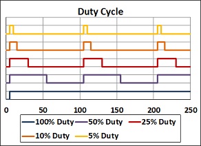
The data sheets of linear or rotary solenoids often contain a table with data for a relative duty cycle of 100%, 50%, 25% and 10% and the corresponding operating voltages. However, this presentation of selected data often does not describe the real application - either a different operating voltage is given for which you have to determine the permissible load cycle or you have to determine the maximum allowed operating voltage for a given load cycle. In this small calculation programme you will find the appropriate tools for both calculations:
In the PDF file on the right, we provide a white paper from Geeplus, which summarises the technical correlations around the topic of load cycle once again.
CALCULATION TOOL FOR THE RELATIONSHIP BETWEEN COIL TEMPERATURE AND RESISTANCE, ESPECIALLY FOR LINEAR AND ROTARY SOLENOIDS
The resistance of any coil depends on the temperature. For electrical actuators such as linear solenoids and rotary solenoids, voice coil actuators and motors, this means that when the motor is loaded, the coil resistance also increases as the coil temperature rises. In the case of solenoids, which are often only operated with a constant voltage, this means that as the temperature rises, the current through the coil decreases due to the higher coil resistance and thus the force of the actuator decreases. The steep characteristic curve of the solenoids when closing the air gap in the direction of the holding position ensures here that no problem usually arises in the holding phase; however, if the solenoid is switched off and cannot cool down completely, problems can arise when it is switched on again if the already weaker starting force is further reduced by the lower current due to the higher coil temperature. The only remedy for constant voltage control is a larger solenoid.
The alternative to constant voltage control would be a current control, because the current in the coil is decisive for the force development of the solenoid. A so-called Pick&Hold-Module is a good solution here; it offers the possibility of overcoming the disadvantages of the characteristic curve of a linear solenoid at the beginning of the energisation with a higher peak current for a defined time and increasing the starting force and then switching back to a reduced holding current in the holding phase; because of the steep characteristic curve of linear solenoids, this can often even be a smaller current than the permissible continuous current, which in turn reduces the average energy consumption and heating. In this way, even a smaller solenoid can often be used. The only prerequisite for this is sufficient voltage to get the desired currents into the winding.
The following small calculation tool allows you to calculate both the temperature of a winding as a function of the change in resistance (e.g. to check what temperature really prevails in the coil itself) and the change in resistance for a given temperature rise. In addition to copper, the coefficients for silver and aluminium are available here!
Coil Temperature Resistance Calculator.
CALCULATION TOOL LINEAR MOTION WITH LINEAR EQUATIONS, ESPECIALLY FOR THE SELECTION OF LINEAR MOTORS AND VOICE COIL ACTUATORS
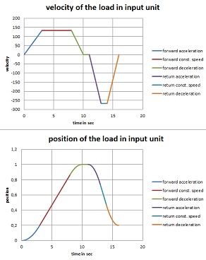
For direct linear movements, linear motors or voice coil motors are possible solutions. With our small linear move calculator we offer a tool for a first rough calculation when selecting suitable actuators; the equations are simple linear equations, but an angle of inclination and also friction and a process force can be taken into account. A small graphic output is integrated; this opens a new window with each click so that different variants can be compared (it is planned to extend this output and to output the data as well, so that a small documentation of the application is created here; you may have to switch off the pop-up blocker to use this function).
An extension to include a frequency based calculation of the movement and a sine oscillation is in preparation.
In addition to the pure equation of motion, we have also included a consideration of the linear motor / voice coil motor: if the first part of the calculation is still about the calculation of the required forces and thus the selection of a suitable motor with regard to the size, the second part of the calculation can immediately include the selection of the amplifier with regard to current and voltage with the help of the winding data.
Please bear in mind that this tool works with simple means. It does not replace the advice of an expert!

CALCULATION TOOL FOR DETERMINING THE RMS VALUE IN DIFFERENT LOAD CYCLE SITUATIONS
The equation for determining an RMS value is well known - a simple tool for calculating this RMS value in different load cycle situations has been missing until now. Our small calculation programme closes this gap with its own approach. First of all, we completely detach ourselves from the physical units - but it is clear that the calculation only makes sense if the input for any amplitude values, must be in the same unit in each case. If we consider currents, for example, and decide on Adc, then all currents must be converted exactly into this unit before the input.
In order to make the tool simple but flexible and also to enable a graphical output, we have imposed the following restrictions on ourselves:
- there are 3 different cycles = segments
- each cycle can contain 5 repetitions
- in each cycle there are 3 phases, if you transfer that to motors: Acceleration (peak), holding phase (constant speed) and pause (rest, possibly with holding force).
- each of these phases has its own time
- for each cycle (segment), a segment time and a segment RMS value are determined and output in the table.
- a total time and a total RMS value are calculated for all segments and output as a red line in the graph

CALCULATION TOOL FOR THE TORQUE REQUIRED FOR FRICTION HINGES
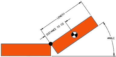
The following calculation tool for friction hinges allows the calculation of the required torque according to the lever law; the load mass is assumed to be a point mass; the distance to the centre of gravity can be entered individually or, if the check mark "equally distributed mass" is set, half the length of the element is assumed here. The input of the angle determines from which angle against the horizontal the load is allowed to drop down - also, of course, the torque of the hinge remains as a counter-torque, i.e. the load mass does not drop down unbraked, but the moment of the load mass prevails from this angle and leads to the downward movement of the load. For the unit for the output of the torque, you can choose between Nm, kgf-cm and lb-in. It can be selected how many hinges the load is distributed on, i.e. which torque is required per friction hinge.
In the PDF file on the right, we have compiled relevant information on the selection of friction hinges.
CALCULATION TOOL FOR DIFFERENT ENGINEERING UNITS
Engineering units and their different use in different regions have caused many an engineering project to fail. Actually, the plan was that we all work in metric units - but we still have a long way to go. We have created a small tool for converting various technical units here - completeness is unfortunately hopeless. However, you are welcome to send us suggestions via our contact form.
Please pay special attention to the setting of the decimal places in this tool, which you can vary at any time.


 PDF Whitepaper Duty Cycle and thermal considerations

 PRINT PAGE |