POWER ELECTRONICS FOR LINEAR AND ROTARY SOLENOIDS
We offer some ready-to-use power electronic circuits for the control of linear solenoids and rotary solenoids:
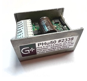
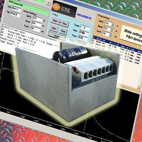
Pick&Hold: these provide a higher current - and thus an increased force - for a defined time when switching on, which is then reduced to the holding value; this makes it possible to compensate for the often unfavorable characteristic force curve of solenoids and to achieve a higher starting force and at the same time reduce the average power and thus the thermal load on the actuator; pick & hold amplifiers can thus enable the use of smaller and also more cost-effective actuators under certain circumstances; when selecting windings, low-resistance windings are used so that the desired coil current or the desired force can be achieved in every situation, even with warm solenoids and the associated higher coil resistance; this is another advantage of pick & hold circuits - as the force is dependent on the current, it is reproducible by the current control and is not subject to the fluctuations caused by the thermal changes in the resistance if only a fixed voltage is applied. The peak time, the peak current and the holding current can be set using software (free of charge, Micro-USB connection).
Pick&Drop: these are driven with a short pulse that provides the voltage for the adjustable time and then switches back to 0V.
PWM (analog): this is the analog control variant; by means of an analog voltage or current input the output voltage can be varied proportionally.
Cyclic on/off: this circuit variant enables the voltage to be switched on/off cyclically; the frequency, the duty cycle and the voltage can be influenced.
Position control: this is a simple controller circuit with PID control for a limited stroke or angle with analog feedback or encoder feedback.


| type | model | voltage Vdc |
continuous current Adc |
peak current Adc |
channels | input signal |
adjustment | feedback | size circuit board mm |
information |
| Pick & Hold | PHu-50 | 8 - 50 | 0.1 - 25 | 0.1 - 25 | 2 bipolar or 2 single channel |
pulse 5 - 24 Vdc |
peak time peak current continuous current (Micro-USB) |
- | 55 x 39 x 29 |
manual Software PHu 8.2 (zip) |
| Pick & Hold | PHu-150 | 16 - 75 | 0.1 - 24 | 0.1 - 24 | 1 | pulse 3 - 30 Vdc |
peak time peak current continuous current (Micro-USB) |
- | 80 x 42 x 32 | manual |
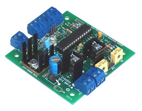
| Pick & Hold | PH-ET-xx | 9 - 50 | 4 | 15 | 1 - 2 | pulse 3Vdc up to supply voltage |
peak time continuous voltage (with 2 potentionmeters on board) |
- | 76.2 x 76.2 x 21.5 |
data sheet wiring diagram |
| Pick & Drop | PDD-01 | 9 - 50 | 4 | 15 | 1 | pulse 3Vdc up to supply voltage |
on time (with potentiometers on board) |
- | 76.2 x 76.2 x 21.5 |
data sheet wiring diagram |
| Proportional | PWM-xx | 9 - 50 | 4 | 15 | 1 - 2 | analog voltage 0 - 5Vdc current 4 - 20mA |
max. voltage (with potentiometers on board) |
- | 76.2 x 76.2 x 21.5 |
data sheet wiring diagram |
| Cyclic on/off | LOC-01 | 9 - 50 | 4 | 15 | 1 | pulse 3Vdc up to supply voltage |
frequency output voltage on time (with 3 potentiometers on board) |
- | 76.2 x 76.2 x 21.5 |
data sheet wiring diagram |


 PRINT PAGE |